

BLDC Motor control using Arduino | Speed control with potentiometer
The brushless dc motor is a three-phase dc motor which requires a controller to power its 3 phases. This controller is called an ESC (Electronic Speed Controller).
This topic shows how to drive a BLDC motor using Arduino where the speed is controlled with a potentiometer.
The brushless dc (BLDC) motor is a 3-phase motor comes in two main types: sensored and sensorless. The sensorless BLDC motor control technique is based on the BEMF (Back Electromotive Force) produced in the stator windings.
In this blog there are many topics show how to control sensored and sensorless brushless DC motors using Arduino and some other PIC microcontrollers.
One of these projects shows how to build a simple ESC using Arduino where the speed of the BLDC motor is controlled with two push buttons.
In this project I’m going to make the same controller but a potentiometer is used instead of the two push buttons.
Related Projects:
The following topic shows more details about the BEMF technique:
Sensorless BLDC motor control with Arduino – DIY ESC
Other BLDC motor project:
Brushless DC motor controller using Arduino and IR2101
In the above two projects, I used the Atmega328P (Arduino UNO microcontroller) internal analog comparator to detect the zero crossing events of the 3 phases, but it’s not a good idea (may give bad results) to use this comparator and the ADC module because they share the same multiplexer. So, I used an external chip which is LM339 quad comparator IC.
Hardware Required:
 Brushless dc motor control with Arduino circuit:
The following image shows project circuit schematic diagram.
Brushless dc motor control with Arduino circuit:
The following image shows project circuit schematic diagram.
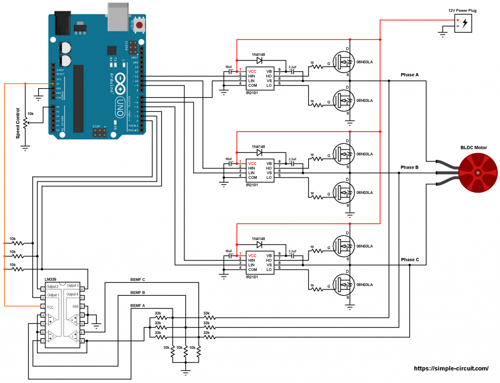 All grounded terminals are connected together.
As mentioned above, the brushless dc motor is a 3-phase motor. In the circuit diagram above the 3 phases are named: Phase A, Phase B and Phase C.
The first three 33k (connected to motor phases) and the three 10k resistors are used as voltage dividers, the other three 33k resistors generate the virtual natural point.
In this project we need 3 comparators to compare the BEMF of each phase with respect to the virtual natural point because we need to detect the zero crossing of each phase, here I used the LM339 quad comparator chip. The virtual point is connected to the inverting input ( – ) of the three comparators as shown in the circuit diagram above. BEMF A is connected to the non-inverting pin ( + ) of comparator number 1, BEMF B is connected to the positive terminal of comparator 2 and BEMF C is connected to the positive terminal of comparator 3. Comparator 4 is not used and its input terminals should be grounded.
As known the comparator output is logic 1 if the non-inverting voltage is greater than the inverting voltage and vice versa.
The LM339 outputs are open collector which means a pull up resistor is needed for each output, for that I used three 10k ohm resistors.
The outputs of the 3 comparators are connected to Arduino pins 2, 3 and 4 respectively for BEMF A, BEMF B and BEMF C.
Arduino UNO pins 2, 3 and 4 are ATmega328P microcontroller external interrupt pins PCINT18, PCINT19 and PCINT20 respectively.
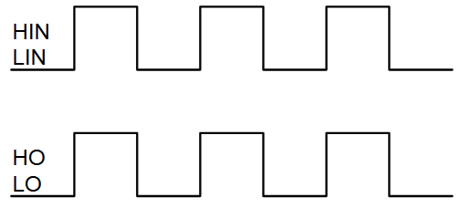
The IR2101 chips are used to control high side and low side mosfets of each phase. The switching between the high side and the low side is done according to the control lines HIN and LIN. The figure below shows input and output timing diagram:
All grounded terminals are connected together.
As mentioned above, the brushless dc motor is a 3-phase motor. In the circuit diagram above the 3 phases are named: Phase A, Phase B and Phase C.
The first three 33k (connected to motor phases) and the three 10k resistors are used as voltage dividers, the other three 33k resistors generate the virtual natural point.
In this project we need 3 comparators to compare the BEMF of each phase with respect to the virtual natural point because we need to detect the zero crossing of each phase, here I used the LM339 quad comparator chip. The virtual point is connected to the inverting input ( – ) of the three comparators as shown in the circuit diagram above. BEMF A is connected to the non-inverting pin ( + ) of comparator number 1, BEMF B is connected to the positive terminal of comparator 2 and BEMF C is connected to the positive terminal of comparator 3. Comparator 4 is not used and its input terminals should be grounded.
As known the comparator output is logic 1 if the non-inverting voltage is greater than the inverting voltage and vice versa.
The LM339 outputs are open collector which means a pull up resistor is needed for each output, for that I used three 10k ohm resistors.
The outputs of the 3 comparators are connected to Arduino pins 2, 3 and 4 respectively for BEMF A, BEMF B and BEMF C.
Arduino UNO pins 2, 3 and 4 are ATmega328P microcontroller external interrupt pins PCINT18, PCINT19 and PCINT20 respectively.
The IR2101 chips are used to control high side and low side mosfets of each phase. The switching between the high side and the low side is done according to the control lines HIN and LIN. The figure below shows input and output timing diagram:
 The HIN lines of the three IR2101 are connected to pins 11, 10 and 9 respectively for phase A, phase B and phase C. The Arduino UNO can generate PWM signals on that pins where only high side mosfets are PWMed.
The LIN lines are connected to Arduino pins 7, 6 and 5 respectively for phase A, phase B and phase C.
The 10k potentiometer is used to vary the speed of the BLDC motor, its output is connected to Arduino analog channel 0 (A0).
Brushless dc motor control with Arduino code:
Arduino pins 9, 10 and 11 can generate PWM signals where pin 9 and pin 10 are related to Timer1 module (OC1A and OC1B) and pin 11 is related to Timer2 module (OC2A). Both Timer modules are configured to generate a PWM signal with a frequency of about 31KHz and a resolution of 8 bits. The duty cycles of the PWM signals are updated when the ADC module completes its conversion by writing to registers OCR1A, OCR1B and OCR2A.
Rest of code is described through comments!
The HIN lines of the three IR2101 are connected to pins 11, 10 and 9 respectively for phase A, phase B and phase C. The Arduino UNO can generate PWM signals on that pins where only high side mosfets are PWMed.
The LIN lines are connected to Arduino pins 7, 6 and 5 respectively for phase A, phase B and phase C.
The 10k potentiometer is used to vary the speed of the BLDC motor, its output is connected to Arduino analog channel 0 (A0).
Brushless dc motor control with Arduino code:
Arduino pins 9, 10 and 11 can generate PWM signals where pin 9 and pin 10 are related to Timer1 module (OC1A and OC1B) and pin 11 is related to Timer2 module (OC2A). Both Timer modules are configured to generate a PWM signal with a frequency of about 31KHz and a resolution of 8 bits. The duty cycles of the PWM signals are updated when the ADC module completes its conversion by writing to registers OCR1A, OCR1B and OCR2A.
Rest of code is described through comments!
The following video shows my simple hardware circuit result:
- Arduino UNO board —-> ATmega328P datasheet
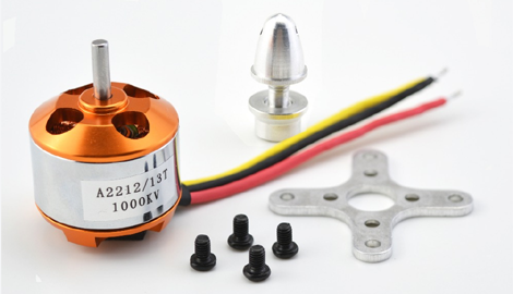
- Brushless DC motor (I’m using A2212/13T 1000KV)
- 6 x 06N03LA N-type mosfet (or equivalent) —-> datasheet
- 3 x IR2101 (or IR2101S) gate driver IC —-> datasheet
- LM339 quad comparator IC —-> datasheet
- 6 x 33k ohm resistor
- 6 x 10k ohm resistor
- 6 x 10 ohm resistor
- 3 x IN4148 diode
- 3 x 10uF capacitor
- 3 x 2.2uF capacitor
- 10k ohm potentiometer
- 12V source
- Breadboard
- Jumper wires
Brushless dc motor control with Arduino circuit:
The following image shows project circuit schematic diagram.
 All grounded terminals are connected together.
As mentioned above, the brushless dc motor is a 3-phase motor. In the circuit diagram above the 3 phases are named: Phase A, Phase B and Phase C.
The first three 33k (connected to motor phases) and the three 10k resistors are used as voltage dividers, the other three 33k resistors generate the virtual natural point.
In this project we need 3 comparators to compare the BEMF of each phase with respect to the virtual natural point because we need to detect the zero crossing of each phase, here I used the LM339 quad comparator chip. The virtual point is connected to the inverting input ( – ) of the three comparators as shown in the circuit diagram above. BEMF A is connected to the non-inverting pin ( + ) of comparator number 1, BEMF B is connected to the positive terminal of comparator 2 and BEMF C is connected to the positive terminal of comparator 3. Comparator 4 is not used and its input terminals should be grounded.
As known the comparator output is logic 1 if the non-inverting voltage is greater than the inverting voltage and vice versa.
The LM339 outputs are open collector which means a pull up resistor is needed for each output, for that I used three 10k ohm resistors.
The outputs of the 3 comparators are connected to Arduino pins 2, 3 and 4 respectively for BEMF A, BEMF B and BEMF C.
Arduino UNO pins 2, 3 and 4 are ATmega328P microcontroller external interrupt pins PCINT18, PCINT19 and PCINT20 respectively.
The IR2101 chips are used to control high side and low side mosfets of each phase. The switching between the high side and the low side is done according to the control lines HIN and LIN. The figure below shows input and output timing diagram:
The HIN lines of the three IR2101 are connected to pins 11, 10 and 9 respectively for phase A, phase B and phase C. The Arduino UNO can generate PWM signals on that pins where only high side mosfets are PWMed.
The LIN lines are connected to Arduino pins 7, 6 and 5 respectively for phase A, phase B and phase C.
The 10k potentiometer is used to vary the speed of the BLDC motor, its output is connected to Arduino analog channel 0 (A0).
Brushless dc motor control with Arduino code:
Arduino pins 9, 10 and 11 can generate PWM signals where pin 9 and pin 10 are related to Timer1 module (OC1A and OC1B) and pin 11 is related to Timer2 module (OC2A). Both Timer modules are configured to generate a PWM signal with a frequency of about 31KHz and a resolution of 8 bits. The duty cycles of the PWM signals are updated when the ADC module completes its conversion by writing to registers OCR1A, OCR1B and OCR2A.
Rest of code is described through comments!
All grounded terminals are connected together.
As mentioned above, the brushless dc motor is a 3-phase motor. In the circuit diagram above the 3 phases are named: Phase A, Phase B and Phase C.
The first three 33k (connected to motor phases) and the three 10k resistors are used as voltage dividers, the other three 33k resistors generate the virtual natural point.
In this project we need 3 comparators to compare the BEMF of each phase with respect to the virtual natural point because we need to detect the zero crossing of each phase, here I used the LM339 quad comparator chip. The virtual point is connected to the inverting input ( – ) of the three comparators as shown in the circuit diagram above. BEMF A is connected to the non-inverting pin ( + ) of comparator number 1, BEMF B is connected to the positive terminal of comparator 2 and BEMF C is connected to the positive terminal of comparator 3. Comparator 4 is not used and its input terminals should be grounded.
As known the comparator output is logic 1 if the non-inverting voltage is greater than the inverting voltage and vice versa.
The LM339 outputs are open collector which means a pull up resistor is needed for each output, for that I used three 10k ohm resistors.
The outputs of the 3 comparators are connected to Arduino pins 2, 3 and 4 respectively for BEMF A, BEMF B and BEMF C.
Arduino UNO pins 2, 3 and 4 are ATmega328P microcontroller external interrupt pins PCINT18, PCINT19 and PCINT20 respectively.
The IR2101 chips are used to control high side and low side mosfets of each phase. The switching between the high side and the low side is done according to the control lines HIN and LIN. The figure below shows input and output timing diagram:
The HIN lines of the three IR2101 are connected to pins 11, 10 and 9 respectively for phase A, phase B and phase C. The Arduino UNO can generate PWM signals on that pins where only high side mosfets are PWMed.
The LIN lines are connected to Arduino pins 7, 6 and 5 respectively for phase A, phase B and phase C.
The 10k potentiometer is used to vary the speed of the BLDC motor, its output is connected to Arduino analog channel 0 (A0).
Brushless dc motor control with Arduino code:
Arduino pins 9, 10 and 11 can generate PWM signals where pin 9 and pin 10 are related to Timer1 module (OC1A and OC1B) and pin 11 is related to Timer2 module (OC2A). Both Timer modules are configured to generate a PWM signal with a frequency of about 31KHz and a resolution of 8 bits. The duty cycles of the PWM signals are updated when the ADC module completes its conversion by writing to registers OCR1A, OCR1B and OCR2A.
Rest of code is described through comments!
|
1
2
3
4
5
6
7
8
9
10
11
12
13
14
15
16
17
18
19
20
21
22
23
24
25
26
27
28
29
30
31
32
33
34
35
36
37
38
39
40
41
42
43
44
45
46
47
48
49
50
51
52
53
54
55
56
57
58
59
60
61
62
63
64
65
66
67
68
69
70
71
72
73
74
75
76
77
78
79
80
81
82
83
84
85
86
87
88
89
90
91
92
93
94
95
96
97
98
99
100
101
102
103
104
105
106
107
108
109
110
111
112
113
114
115
116
117
118
119
120
121
122
123
124
125
126
127
128
129
130
131
132
133
134
135
136
137
138
139
140
141
142
143
144
145
146
147
148
149
150
151
152
153
154
155
156
157
158
159
160
161
162
163
164
165
166
167
168
169
170
171
172
173
174
175
176
177
178
179
180
181
182
183
184
185
186
187
188
189
190
191
192
193
194
195
196
197
|
/* Sensorless brushless DC motor control with Arduino UNO and IR2101 (Arduino DIY ESC).
* BLDC motor speed is controlled with a potentiometer connected to A0.
* This is a free software with NO WARRANTY.
* http://simple-circuit.com/
*/
#define PWM_MAX_DUTY 255
#define PWM_MIN_DUTY 50
#define PWM_START_DUTY 100
byte bldc_step = 0, motor_speed, pin_state;
void setup()
{
DDRD |= 0xE0; // configure pins 5, 6 and 7 as outputs
PORTD = 0x00;
DDRB |= 0x0E; // configure pins 9, 10 and 11 as outputs
PORTB = 0x31;
// Timer1 module setting: set clock source to clkI/O / 1 (no prescaling)
TCCR1A = 0;
TCCR1B = 0x01;
// Timer2 module setting: set clock source to clkI/O / 1 (no prescaling)
TCCR2A = 0;
TCCR2B = 0x01;
// ADC module configuration
ADMUX = 0x60; // configure ADC module and select channel 0
ADCSRA = 0x84; // enable ADC module with 16 division factor (ADC clock = 1MHz)
PCICR = EIMSK = 0; // disable all external interrupts
pinMode(2, INPUT_PULLUP);
pinMode(3, INPUT_PULLUP);
pinMode(4, INPUT_PULLUP);
}
// pin change interrupt 2 (PCINT2) ISR
ISR (PCINT2_vect)
{
if( (PIND & PCMSK2) != pin_state )
return;
// BEMF debounce
for(byte i = 0; i < 20; i++)
{
if(bldc_step & 1){
if(PIND & PCMSK2) i -= 1;
}
else {
if(!(PIND & PCMSK2)) i -= 1;
}
}
bldc_move();
bldc_step++;
bldc_step %= 6;
}
// BLDC motor commutation function
void bldc_move()
{
switch(bldc_step)
{
case 0:
AH_BL();
BEMF_C_FALLING();
break;
case 1:
AH_CL();
BEMF_B_RISING();
break;
case 2:
BH_CL();
BEMF_A_FALLING();
break;
case 3:
BH_AL();
BEMF_C_RISING();
break;
case 4:
CH_AL();
BEMF_B_FALLING();
break;
case 5:
CH_BL();
BEMF_A_RISING();
}
}
void loop()
{
SET_PWM_DUTY(PWM_START_DUTY); // setup starting PWM with duty cycle = PWM_START_DUTY
int i = 5000;
// motor start
while(i > 100)
{
delayMicroseconds(i);
bldc_move();
bldc_step++;
bldc_step %= 6;
i = i - 20;
}
motor_speed = PWM_START_DUTY;
PCICR = 4; // enable pin change interrupt for pins PCINT23..16 (Arduino 0 to 7)
while(1)
{
ADCSRA |= 1 << ADSC; // start conversion
while(ADCSRA & 0x40); // wait for conversion complete
motor_speed = ADCH; // read ADC data (8 bits only)
if(motor_speed < PWM_MIN_DUTY)
motor_speed = PWM_MIN_DUTY;
SET_PWM_DUTY(motor_speed);
}
}
void BEMF_A_RISING()
{
PCMSK2 = 0x04; // enable Arduino pin 2 (PCINT18) interrupt, others are disabled
pin_state = 0x04;
}
void BEMF_A_FALLING()
{
PCMSK2 = 0x04; // enable Arduino pin 2 (PCINT18) interrupt, others are disabled
pin_state = 0;
}
void BEMF_B_RISING()
{
PCMSK2 = 0x08; // enable Arduino pin 3 (PCINT19) interrupt, others are disabled
pin_state = 0x08;
}
void BEMF_B_FALLING()
{
PCMSK2 = 0x08; // enable Arduino pin 3 (PCINT19) interrupt, others are disabled
pin_state = 0;
}
void BEMF_C_RISING()
{
PCMSK2 = 0x10; // enable Arduino pin 4 (PCINT20) interrupt, others are disabled
pin_state = 0x10;
}
void BEMF_C_FALLING()
{
PCMSK2 = 0x10; // enable Arduino pin 4 (PCINT20) interrupt, others are disabled
pin_state = 0;
}
void AH_BL()
{
PORTD &= ~0xA0;
PORTD |= 0x40;
TCCR1A = 0; // turn pin 11 (OC2A) PWM ON (pin 9 & pin 10 OFF)
TCCR2A = 0x81; //
}
void AH_CL()
{
PORTD &= ~0xC0;
PORTD |= 0x20;
TCCR1A = 0; // turn pin 11 (OC2A) PWM ON (pin 9 & pin 10 OFF)
TCCR2A = 0x81; //
}
void BH_CL()
{
PORTD &= ~0xC0;
PORTD |= 0x20;
TCCR2A = 0; // turn pin 10 (OC1B) PWM ON (pin 9 & pin 11 OFF)
TCCR1A = 0x21; //
}
void BH_AL()
{
PORTD &= ~0x60;
PORTD |= 0x80;
TCCR2A = 0; // turn pin 10 (OC1B) PWM ON (pin 9 & pin 11 OFF)
TCCR1A = 0x21; //
}
void CH_AL()
{
PORTD &= ~0x60;
PORTD |= 0x80;
TCCR2A = 0; // turn pin 9 (OC1A) PWM ON (pin 10 & pin 11 OFF)
TCCR1A = 0x81; //
}
void CH_BL()
{
PORTD &= ~0xA0;
PORTD |= 0x40;
TCCR2A = 0; // turn pin 9 (OC1A) PWM ON (pin 10 & pin 11 OFF)
TCCR1A = 0x81; //
}
void SET_PWM_DUTY(byte duty)
{
OCR1A = duty; // set pin 9 PWM duty cycle
OCR1B = duty; // set pin 10 PWM duty cycle
OCR2A = duty; // set pin 11 PWM duty cycle
}
|